Binary 10/4 configuration
Click on the desired Binary 10/4 in the device list to go to its configuration page. All relevant information about the device is displayed there.
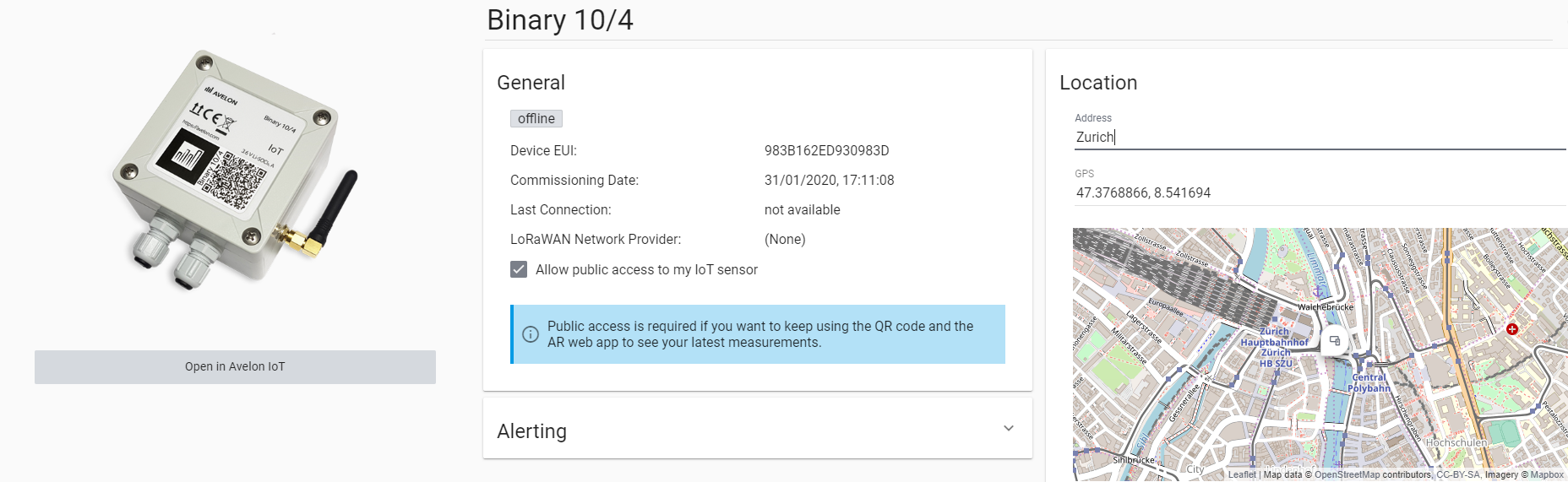
Detailed view of a Binary 10/4
General
- Device EUI
The device EUI is used to uniquely identify the device. You can also find the device EUI on the label on the back of the device.
- Activation Date
The date the device was registered on the system.
- Last Connection
Indicates when the device last connected to the Avelon server.
- LoRaWAN
- LoRaWAN Network Provider
Indicates which LoRaWAN network provider the device is currently registered with. To learn how to change your network provider, see LoRaWAN network provider.
- Application EUI
The EUI of the application on the LoRaWAN server to which this device is assigned. Only available if the device is self-managed.
- Application Key
The key of the application on the LoRaWAN server to which this device is assigned. Only available if the device is self-managed.
- Application ID
The ID of the application on the LoRaWAN server to which this device is assigned.
- Allow access to this device in the public web app without login
If you want to use the QR code on the device to quickly access its measurements, keep this option enabled. However, this will make the device accessible on iot.avelon.cloud to anyone who has access to the QR code. If you deactivate the option, the device and its measurements can only be accessed when you’re logged in. You can change this setting at any time.
Location
- Address
The location address of the device. If you fill in this field, the device will be displayed on the map widget and in the map navigation.
- GPS
If the address input above is insufficient, you can also specify the location of the device using GPS coordinates.
Device access
Here you configure which user groups are allowed to access the device and its data points. If users should see data points or their recordings or live values, they need to have access to the respective device on which these data points are located.
To add a user group, click on Add User Group and select a user group from the list. All users in that user group will get access to the device. To remove a user group, click on Remove next to the corresponding user group.
Granting access to a device also enables access to the device via our public API.
Note that users with the action right “Show all devices” can see all devices of the client, regardless of their respective user groups.
Alerting
- Enable Watchdog
Activate the watchdog to be notified if the device does not report in for a longer period of time. This allows you to react in time in the event of a device defect or insufficient transmission power. Select the desired alarm chain from the dropdown.
Warning
Watchdog alarm tickets cannot be closed until the device sends an acknowledgment that the alarm is gone and that the connection with the server is reestablished. As a result, when trying to close a ticket prior to device acknowledgment, the following error message is displayed: “This ticket cannot be closed. The alarm must be acknowledged by the device first”.
- Enable Battery Alarm
Activate the battery alarm to be notified if the battery falls below a certain threshold. Select the desired alarm chain from the dropdown.
Pulse valence of counters
Because the raw value that is sent from a counter does not necessarily represent the actual energy consumed, it is converted according to the following calculation:
\(v_{new}\) |
New converted record that will be stored in the database in the unit of the data point. |
\(v_{prev}\) |
Previous converted record that was stored in the database in the unit of the data point. |
\(cntr_{cur}\) |
Current raw counter value that was received from the device. |
\(cntr_{prev}\) |
Previous raw counter value that was received from the device. |
\(pv\) |
Pulse valence (multiplication factor). |
The pulse valence can be configured on the respective data point (see below).
If you use surrogate BACnet objects for your Binary 10/4 counters, note that the values of these BACnet objects correspond to the raw values from the counters, not the converted values of the data points.
Set up pulse valence of counters
On counter data points, you can configure their pulse valence, i.e. the amount the data point value should be increased with every pulse. The available data points are displayed on the Data Points card. To configure the pulse valence for one of the counter data points, proceed as follows:
Go to the details view of a counter data point by clicking Go to Data Point next to it on the Data Points card.
Note
Counter data points have the icon and are usually called
Input x Counter. Data points with the icon and without the suffixCounterare their binary counterparts.On the Settings card of the counter data point, configure the following properties:
- Data Type
This is needed to select the appropriate unit below. Commonly used data types are Energy, Volume or Timespan.
- Pulse Valence
The amount the counter should be increased with every pulse. Has to be entered in the unit set in Default Unit.
- Default Unit
Select the unit of the counter data point. The pulse valence has to be provided in this unit. If you want the value to be displayed in a different unit on widgets, you can also set a Display Unit, although this is optional.
If you want to adjust the current value of the counter data point, go to the Measurements tab at the top and add a new manual measurement as described here. In contrast to values received from the device, manually added values are not going to be converted with the conversion function mentioned above.
Set up alarm on binary input
You can set up an alarm for the binary data points of a Binary 10/4. The available data points are displayed on the Data Points card. To set up an alarm for one of the input data points, proceed as follows:
Go to the details view of a binary data point by clicking Go to Data Point next to it on the Data Points card.
Note
Binary data points have the icon and are usually called
Input x(without any additional suffix). Data points with the icon and with suffixCounterare used to count pulses. Alarms have to be configured on the binary data points.Under Reporting and Alerting, define the alert.
- Enable data point
The data point must be enabled with this option if you want it to report changes of value or raise an alarm.
- Minimum and Maximum Reporting Interval
The minimum and maximum reporting interval of the data point. Measurements are reported at least once every maximum reporting interval, but no more than every minimum reporting interval.
- Polarity
The polarity defines the contact’s normal position. For Normally Open, the value of the data point is 0 when the contact is open and changes to 1 when the contact is closed. For Normally Closed, the value of the data point is 0 when the contact is closed and changes to 1 when the contact is opened (inverted polarity).
- Edge Selection
Determine how edges will be detected: Falling Edge (transition from 1 to 0), Rising Edge (transition from 0 to 1) or Rising and Falling (both). Polling lets you check if the detected value is present for at least the duration of the minimum reporting interval. However, for regular edge selection, polling is not required.
- Debounce Period
The time in milliseconds after a change of value during which no further changes are registered.
Select the alarm chain to be invoked in the event of the alarm. For information on how to set up alarm chains, see Alarm chains.
Note
If you select Suppress alarm, alarms will generate tickets, but no alarm chain will be triggered.
Save your changes by clicking on Save at the top right in the toolbar.
Warning
If you only have a free Heads-up! license on your device, only alarm chains with one user and email notification can be selected. In order to add more users to the alarm chain and to receive alarm notifications via SMS also, a paid Heads-up! license needs to be purchased.
Note
To purchase additional licenses for the device, please click Shop, available on the Licenses card. You will then be redirected to the Avelon Shop. This function is only available on Avelon Cloud.
Gateways
The LoRaWAN gateways with which the sensor was recently in contact are displayed on the map. For a gateway to be displayed correctly, the operator of the gateway must have stored the correct GPS coordinates on the device.
Download labels
You can download or print the labels, which are factory affixed to the outside of the case, at any time. Different labels are available depending on the device type. The front label contains the QR code needed to use the device in our IoT app as well as a marker used in connection with its augmented reality function. The back label contains technical information about the sensor, such as the serial number or device EUI.
You can download or print the two labels by clicking on More at the top right, then on Front Label or Back Label respectively, and then on either Download or Print.
Schematic link
It is possible to jump directly from the IoT app, which you can open via the QR code of one of our IoT devices, to a specific schematic, for example to control the parameters of the air conditioning system. You can specify which schematic is to be opened under Schematic Link.
If you also select a data point filter, the system will try to dynamically fill the data points on the schematic using this data point filter. However, this only works if the system names in the shapes used are set in such a way that a unique assignment of data points from the selected data point filter to the shape is possible.
As soon as the link is set up, a corresponding link to the schematic appears on the IoT app.
Licenses
See Licenses.