Define behavior
Create and test behavior rules
After you have created a new shape or selected an existing one in the Shape Editor, you can define how it should behave based on the values of data points and other properties.
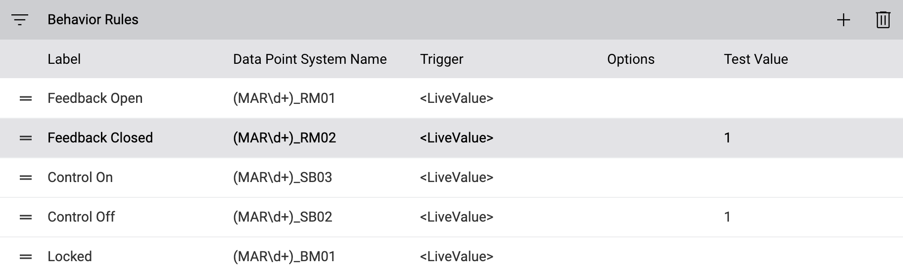
The behavior editor in the lower half of the shape editor is split into two areas, Behavior Rules on the left and Behavior Rules Settings on the right. Essentially, each row under Behavior Rules represents a trigger that has one or more actions attached to it. In most cases, triggers are related to properties of data points. These properties will also be displayed on the faceplate on the schematic when the shape is clicked by the user.
Let’s go through an example to see how behaviors can be defined.
Create a new behavior rule for the shape by clicking on Add New Behavior Rule in the lower half of the screen, right above the table on the left.
Add a new behavior rule to your shape.
A new row appears in the table. Depending on the type of shape you’re currently editing, the new item contains different columns. On the right, you can edit these properties:
- Label
This label is representative of the function of the behavior and will be displayed on the faceplate on the schematic. In most cases, you should use something like “Measured Value”, “Operation Feedback”, “Alarm”, etc.
Note
When assigning labels, note that you can use the same label for several behavior rules. On the schematic, all behavior rules with the same label that use the same data point property are collapsed to a single entry.
- System Name
Parts of a plant identification name to facilitate the placement of data points. See System name in behavior rules for more details.
- Trigger
The trigger used for the behavior. See Triggers for more details.
- Property
Only available if Trigger is set to Data point property or Shape property. The property whose value is used to control the behavior.
- Data point required to pass the quality check
If this checkbox is selected, it is mandatory for a data point to be placed on this behavior rule for the automatic check of the data point assignments to be successful. For more information about automatically checking data point assignments, see Check data point assignments.
- Create data point shape when data point is placed
If this checkbox is selected, a shape is created automatically for this data point if a data point is dropped on this entry on the schematic. This causes additional shapes to be generated when placing data points, which is of particular interest for shapes whose underlying data points are to be visualized separately on the schematic (e.g. for temperature sensors).
- Do not allow changing the data point value
If this checkbox is selected, the value of the assigned data point cannot be edited on the faceplate that appears when the user clicks on the shape on the schematic.
- Hide data point property in compact view
If this checkbox is selected, the property of the assigned data point is not displayed on the compact view of the faceplate that appears when the user clicks on the shape on the schematic. In combination with the action right “Show extended faceplate”, it is possible to hide certain properties from less privileged users while still making them available to users who can toggle the faceplate to the extended view.
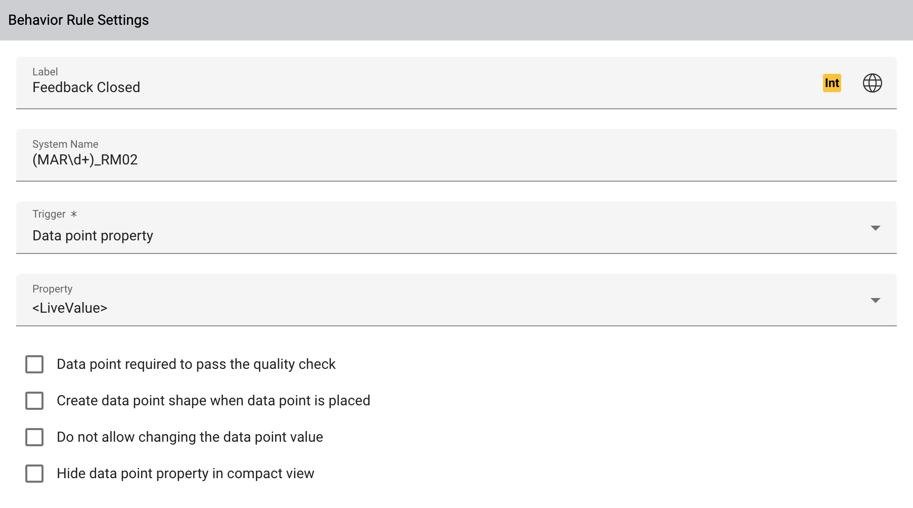
Behavior rule settings for a regular shape
Note
Shapes for single data points only have two settings, Trigger and Property, since all behavior rules refer to the same data point.
Under Behavior, just below Behavior Rule Settings, configure the desired condition when the action should be applied. See Data point conditions and properties for a detailed description of the most frequently used properties.
At the top right, switch to the Code tab to edit the SVG code of your shape. Add a unique id attribute to the element you want to animate, and make sure you set an initial value to the attribute that you want to animate:
<rect id="SomeRectangleID" fill="white" width="100" height="20" />
The specified ID can now be used in your behavior to change the appearance of the shape.
In the Behavior panel at the bottom right, select the option Set shape attribute from the dropdown Action Type. From the dropdown Element, select the ID you’ve just set.
Select the attribute you want to animate from the Attribute dropdown. Note that only attributes are listed which are used in the SVG code of the element. Then select the desired value of the attribute.
If you want to bind multiple actions to the same condition, click on Add Action and define another action. See Actions for a detailed description of all available actions.
If you have defined several behavior rules that change the same property of the same shape element, you can manually set priorities with the field Priority. Actions with a higher priority override actions with a lower priority if both actions are to be applied at the same time.
Note
Consider giving your alarm states a high priority to prevent them from being overridden by lower-priority actions.
Simulator
You can test the shape behavior directly in the shape editor at any time.
Activate the simulator with Start Simulator on the shape preview.
Now enter a test value for the behavior rule in the Test Value column of the list of behavior rules. You can now check whether the behavior is executed as expected.