Modbus RTU
This chapter describes how to configure the Modbus RTU service on the Beetle and how to read and change the network objects.
Please ensure that your Beetle is in operation and has a connection to the Avelon server.
If this is not the case, start in the chapter Connectivity. In order to use the Modbus RTU service and read network objects, a valid licence key must be stored and the service must be enabled.
How to enable or license communication protocol services is described in section Communication protocols. Note To configure the Modbus RTU service, you must have operator privileges. Click on Modbus RTU on the left. Click on the Settings button to open the communication settings of the Modbus RTU service and edit the parameters. Symbol rate (step rate) of data transmission When Even or Odd parity is selected, the number of 1-bits in the data portion of each character frame is counted.
The parity bit is set to 0 or 1 depending on whether the number of 1-bits is even or odd. Set this property to 8 by default for Modbus RTU. Set the stop bits to 1 if Parity is set to Even or Odd, or to 0 if it is set to None. Confirm the changes by clicking on OK. To define which devices, slaves and objects you want to access through Modbus, click on the Configuration files button. In the dialog, click the Upload Configuration File button to upload a new XML configuration file.
You can always delete configuration files that have already been uploaded by clicking the Delete button or download them to your computer by clicking the Download button. Note The configuration files are used to define the objects that are offered via the Modbus RTU service.
The object list is stored statically and not dynamically queried by the bus. For a list of the supported data types, see Supported Modbus data types. For a list of possible error codes, see Modbus error codes. For information on how to connect a Modbus RTU plug to the COM2 port, see Connect Modbus RTU bus to the Beetle. The configuration file for Modbus must be created in a specific XML format.
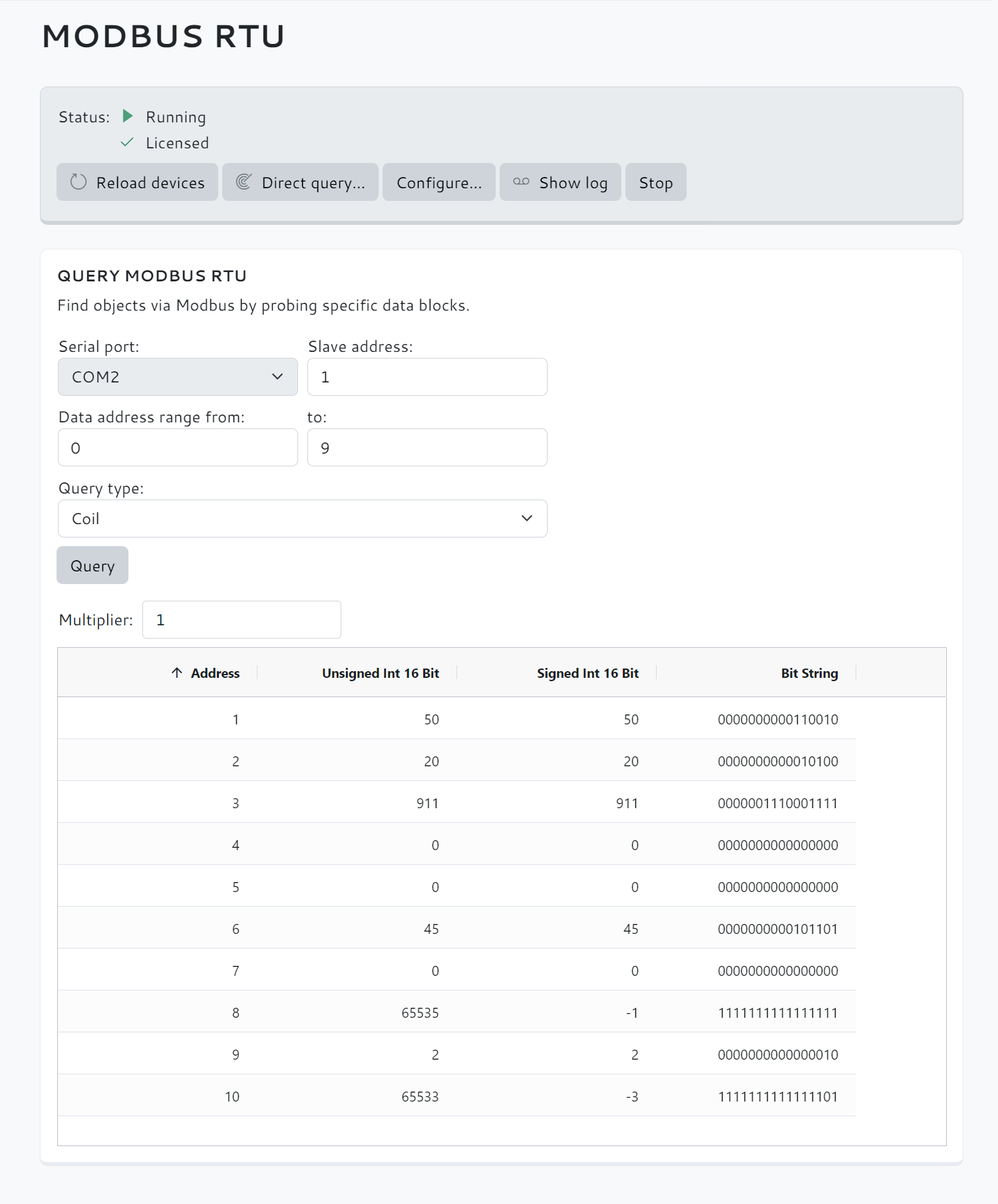
With the Avelon Modbus Configurator, an Excel-based workbook, such configuration files can be created semi-automatically. Open the Avelon Modbus Configurator in Excel. Click on the Neues Blatt (New Sheet) button to create a new Modbus configuration. First configure the connection data to the target device in the upper section. For each object use a new row and fill in all fields. You can decide whether only the current worksheet or all worksheets of the current folder are to be exported. To check whether the objects can be read correctly via Modbus RTU, click the Direct query… button. In the following dialog you can set which address range is to be read out and how the individual bytes are to be interpreted. The serial port through which the Modbus device can be reached.
Currently only COM2 is available. The device number of the Modbus device to be queried. Start and end address of the range to be queried. Select the data type that should be used to query the values.
Coil or Discrete Input will query single bits, while Input Register or Holding Register will query entire registers. Select the size of the registers in bits. 16 (= 2 Bytes) 32 (= 4 Bytes) 64 (= 8 Bytes) Select in which order the individual bytes are stored in memory. Big endian: The most significant byte is stored at the smallest memory address. Little endian: The most significant byte is stored at the largest memory address. If you want to query registers with more than 16 bits, you can select the order of the individual words in memory. Big endian: The most significant word is stored at the smallest memory address. Little endian: The most significant word is stored at the largest memory address. Then click the Query button to read the address range.
The result is displayed in a table below the search mask.
Further display options are now available below: The values read out are multiplied by this number.
Use this function if the actual value is a multiple of the stored value. On the Modbus RTU page, click the Reload gateways button to reload the gateways and objects that you have previously configured using the uploaded configuration files. Note If you receive the message “Please start the Modbus RTU service to display objects on the network.”, you must first enable the Modbus RTU service (see Enable Modbus RTU service). The gateways from the uploaded configuration files are displayed immediately.
Select one of the gateways to display its devices.
Then click one of the devices to list the objects defined on it. Note Use this list to check that all items are available as expected.
Only then should you adjust the data points via the Avelon user interface. After successful object retrieval, click the Download button to download the list of objects to your computer as a CSV file.Enable Modbus RTU service
Configure Modbus RTU service
Create configuration file
Query bus addresses directly
Show objects
Download data point list (optional)