Edit data points
Click on a data point in the data point list to display further information about it. Most of them can also be changed. Data points of different device types can have different setting options.
Note
Don’t forget to save your changes by clicking Save at the top right in the toolbar.
Warning
Changes that you make to data points in the Data Points and Filters tab are not written to the controller. They only affect the display of the data point within the Avelon control system. Note that changes are overwritten if necessary when the data points are synced with the controller again.
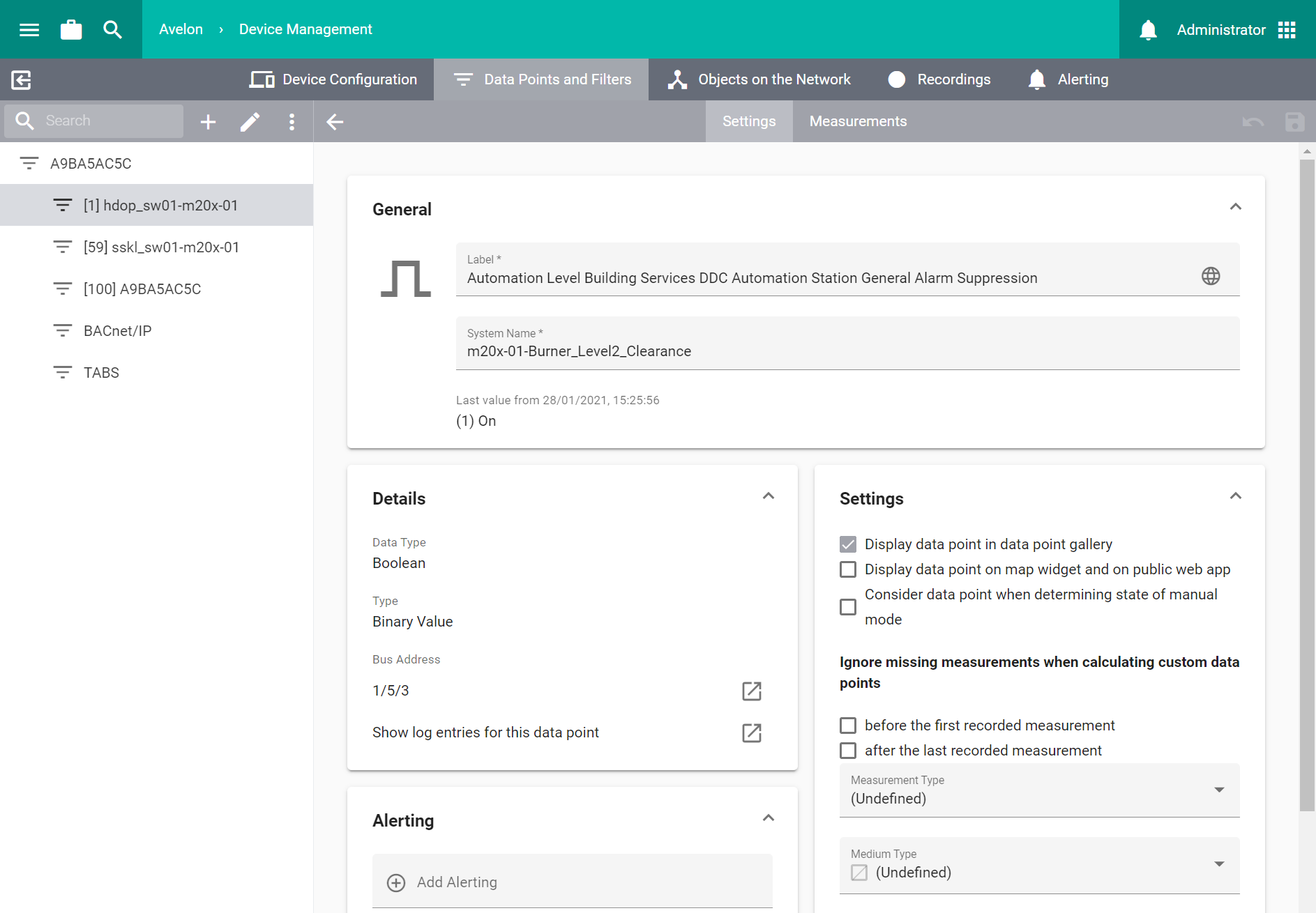
General
- Label
The human-readable name of the data point. It is displayed everywhere where your data point is used.
- System Name
The systematic name of the data point that uniquely identifies it in the entire project. This is also known as the plant identification code and usually contains encoded information about the data point’s location, type and usage and must be unique.
- Last Value
If available, the last known value of the data point is displayed here.
If the data point is writable and you have the appropriate rights, you can also manually enter a new value by clicking on Add Measurement. When adding a value to an energy data point manually, a basic check is performed to ensure the plausibility of the new value. For data points representing energy meters, the new value must be within ∓10% of the linear extrapolation of all previous measurements. For data points representing energy consumption, the new value must be within ∓10% of the average of all previous measurements. If the new value lies outside of this range, a warning will be displayed. The warning should prevent you from entering wrong values, but it can be ignored if you are sure that the entered value is correct.
Details
- Data Type
The type of the data point or the recorded measured variable.
- Type
The bus-specific type of the referenced bus object.
- Bus Address
The bus-specific address of the referenced bus object. Depends on the underlying bus or protocol.
Bus or protocol
Format
BACnet
{DeviceID}/{ObjectType}/{ObjectInstance}
IoT
IOT-{DataPointID}
M-Bus
{Address}-{Instance} or {SecondaryAddress}-{Instance}
Modbus RTU
{SerialPort}/{SlaveID}/{ObjectType}/{Address}/{BitIndex}
Modbus TCP
{IP}:{Port}/{SlaveID}/{ObjectType}/{Address}/{BitIndex}
OPC UA
{ServerID}/{NodeID}
S7
S7/{DataPointID}
TABS
{Type}/{Instance}
Display
- Display in data point sidebar
This data point is displayed in the data point sidebar and can therefore be used in widgets. Data points that are displayed in the data point sidebar are counted against the quota of licensed data points.
- Display on map widget and on the public web app
When you click the device on the map widget, the live value of that data point is displayed in the sidebar that is then shown, and you can view its latest recorded values there directly. For IoT devices, the data point is also displayed on the public web app when you scan the QR code of the device on a smartphone if the option “Make my IoT sensor publicly accessible” is enabled on the device itself.
- Display in Avelon Meters
This data point will be displayed in the Avelon Meters app.
- Default Unit
The unit in which measurements are processed by the bus object.
- Display Unit
The unit in which measurements are displayed.
- Decimal Places
The number of decimal places to be displayed when displaying live values. This figure has no effect on the accuracy of any calculations.
Live Value Profile
Live value profiles can be used to regulate how live values should be displayed or to limit the range of allowed input values. There are two different types of live value profiles:
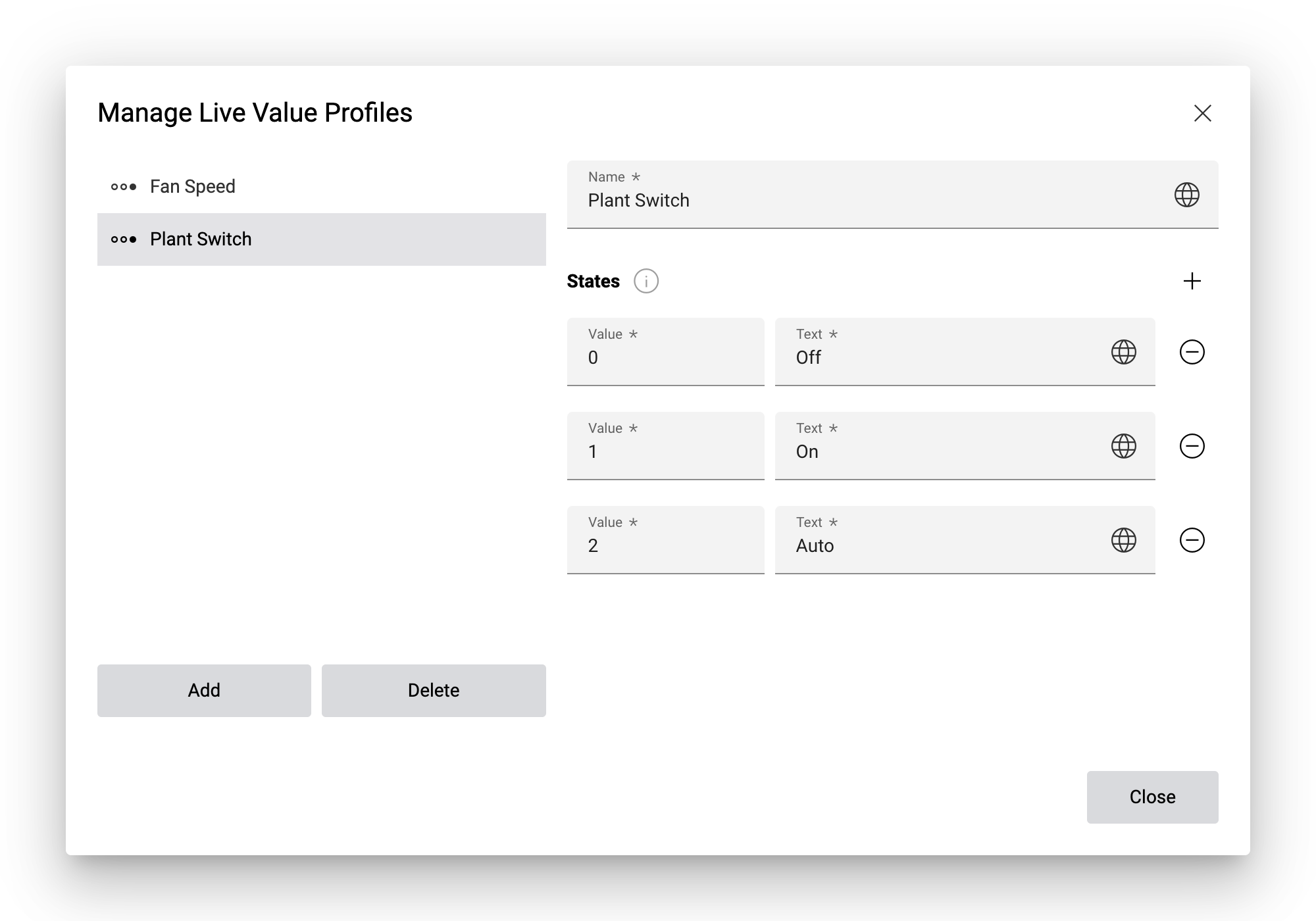
- State profile
State profiles allow you to define a mapping between numeric values of a digital or multistate data point and their textual representation that should be displayed to the user in place of the value. State profiles can only be assigned to data points that don’t have a unit.
- Range profile
Range profiles can be used to limit the range of allowed input values for analog data points. They can only be assigned to writable data points.
To assign a live value profile to the data point, just select it in the Profile dropdown. The same live value profile can be assigned to multiple data points at once. The name of the assigned profile will also be displayed in the Live Value Profile column on the data point list.
To manage your live value profiles, proceed as follows:
Click on Manage Live Value Profiles next to the Profile dropdown.
In the following dialog, all existing profiles are listed on the left. If you select a profile, its details will be displayed on the right.
Add a profile by clicking on Add and then on Range Profile or State Profile, respectively. Enter a name for the new profile.
On state profiles, you can add as many states as you need by clicking on Add State. Enter the value of the state and its textual representation.
On range profiles, you can define the Minimum and Maximum Value and the Step Increment. These are used to limit the user when entering new values for the data point, for example on the Schematic widget.
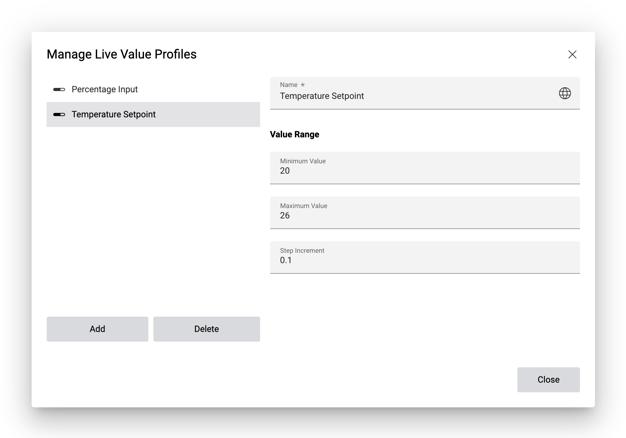
Click on Close to close the dialog.
Assign the new profile to the data point by selecting it from the Profile dropdown.
Measurement Profiles
Measurement profiles allow you to define how specific data points should be displayed when they’re placed in a Measurement Chart widget, how their reference line and forecast should be calculated, and at what thresholds it should raise an alarm.
Before you can assign measurement profiles to a data point, you need to create them first. Click on Manage Profiles at the bottom right of the card to go to the Measurement Profiles view.
Each data point has the following settings where you can assign measurement profiles:
- Visual Profile
The visual profile determines the default appearance of this data point when it is placed in a Measurement Chart widget. This makes it a lot easier to use the data point in charts, since it will always be displayed in the same way according to the settings from the visual profile. However, these settings can still be overwritten on each plot if necessary.
In this dropdown, you can only select measurement profiles of type Visual Profile (green).
- Reference Line
A reference line represents the expected or historical trend of measurements based on previous values. It serves as a benchmark or baseline against which new measurements are compared.
You can select a measurement profile of type Comparison Profile (orange) in this dropdown to define how the reference line of this data point should be calculated.
- Forecast
A forecast represents the expected future values of a data point based on historical data.
You can select a measurement profile of type Comparison Profile (orange) in this dropdown to define how the forecast of this data point should be calculated.
- Alerting
You can select one or multiple measurement profiles of type Comparison Profile (orange) in this dropdown to define the thresholds at which this data point should raise an alarm.
These alarm conditions will be checked regardless of whether the data point is used on a Chart widget or not.
In addition to the measurement profiles, you can also assign one or multiple anomaly checks to the data point:
- Anomaly Checks
The system can check incoming measurements of this data point for anomalies. If an anomaly is detected, the system will automatically flag the respective values as disturbed (see Metering Code Schweiz).
You can select any number of anomaly checks for each data point. The following detection algorithms are available:
- Zero and Negative Values
Values that are zero or negative will be flagged as disturbed. This is useful for data points that should only have positive measurements, such as data points recording energy or water consumption.
- Grubbs’s Test
Detects outliers among the data point measurements according to their normal distribution, which is calculated based on the last 1,000 values, and flags them as disturbed values.
Note that Grubbs’s test will only check for anomalies if the data point contains more than 20 measurements.
If you want to exclude specific measurements from the selected anomaly checks, you can do so by selecting the option Ignore in Anomaly Checks on the respective measurement. See Edit measurements for more information.
Advanced
- Consider data point when determining state of manual mode
Deactivate this option if you do not want the manual mode state of this data point to be displayed on the schematic.
- Ignore missing measurements when calculating data points
When calculating data points, the values of all input data points must be available in the calculation period, and those values must all be recorded in the same minute (UTC). If measurements are missing for some data points in the calculation period, the calculation will fail and no output values will be calculated.
If you want the system to assume missing measurements as null values (0) in your calculations, you can enable these options. The first checkbox will force the system to use the value 0 in any calculation that is performed before the first measurement of this data point. Conversely, the second checkbox will force the system to use the value 0 in any calculation that is performed after the last measurement of this data point.
With these options enabled, the calculation will always generate an output value, even if some data points don’t have values for a specific aggregation interval. Note that the result might not always be as expected, though. In particular, using 0 values in calculations involving multiplications or divisions might lead to undesired side effects.
- Measurement Type
For water and electricity meters, you can speficy the type of the measurements, i.e. whether the values are provided as raw Meter values or as a Consumption. This setting can help Avelon improve the workflow when working with meters, for example it can automatically configure the plot settings when a meter is placed on a chart.
- Medium Type
The medium type that is measured by this data point. The medium type is used in ESG/media reporting and in the Meter network.
You can choose between the following types:
(Undefined)
Acid
Base
Cold Water
Compressed Air
Cooling Brine
Cooling Gas
Cooling Water
District Heating
Electric
Gas
Heating Condensate
Heating Water
Hot Water
Neutral
Oil
Steam Heating
Waste Water
- Medium Type Usage
With the medium type usage, you can define the specific usage of the medium type above. This option is only available for medium types Electric, Oil, Gas, District Heating, Heating Water and Cold Water.
For Oil, Gas, District Heating, Heating Water and Electric, you can choose between
Room Heating
Domestic Hot Water
Room Heating and Domestic Hot Water
For Electric and Cold Water, you can choose between
Tenant
General
Tenants and General
For information about the pulse valence on counter data points of Binary 10/4 devices, please see Set up pulse valence on counters.
Alerting
Various device types
- Suppress alarm
If this option is enabled, every ticket created for this data point will be closed at once automatically. There is neither an escalation of the alarm chain nor a notification of the users, but the ticket is still visible in the ticket list.
Beetle
- Alerting
All alarms are listed here in which this data point is contained. If you remove alarms from this list or add a new alarm, the data point is added to or removed from the selected alarm accordingly. For information on how to configure alarms, see Alerting.
Wisely
Define an upper and/or lower alarm limit value and select the alarm chain to be invoked in the event of an alarm. With the value Deadband for gone alarms relative to the limits, you can also set the difference relative to the alarm limit value as of which any alarm that occurs should automatically be marked as “gone” by the system.
CO₂/VOC sensor settings
In order to conserve battery, you can disable the measurement of CO₂ and VOC sensors when the light density is below a certain threshold. Enable the option and enter the threshold value in lux on the CO₂ or VOC data point. If enabled, no measurements will be recorded or transmitted while the light density is below the given threshold value.
CO₂ sensor calibration
With firmware 3.2.20 and above, Wisely performs an automatic baseline correction (ABC) every 14 days. The lowest CO₂ sample taken over the last 14 days is stored and it is assumed that this low value is equal to 400 ppm, so subsequent measurements are shifted accordingly. You can also trigger a manual calibration of the CO₂ sensor after you have moved the device to a new location. On the data point page of the CO₂ data point, scroll down to CO₂ Sensor Calibration, select Perform Automatic Baseline Correction from the dropdown and click Execute. The process might take a while and will be completed when the device sends an acknowledgment during the next regular data transmission, or if you manually press the reset button on the device. If you select the option Reset to Factory Calibration and press Execute, the calibration will be reset to the factory setting.
Measurement recording
Wisely AllSense devices with a Building Automation license allow you to record measurements of each data point individually.
- Record Periodically
A measurement value will be recorded every \(n\) samples. If the device samples values every 3 hours and you set this period to 4, a measurement will be recorded and transmitted every 12 hours.
- Record Change of Value
A measurement value will be recorded every time the value changes. Enter the lowest amount that a value needs to change in order to register as a change of value.
LeakSense
The data points which measure the electrical resistance, and thus a possible presence of water, can be configured with an alarm. Either select the appropriate water type so that the expected electrical resistance is entered automatically, or enter the value of the electrical resistance directly yourself. Then select the alarm chain to be invoked in the event of an alarm. Under Delay before alarm or a device acknowledgement is triggered, you can define how long the alarm or acknowledgement state should be present before an alarm or acknowledgement is actually invoked. With the value Deadband for gone alarms relative to the limits, you can also set the difference relative to the alarm limit value as of which any alarm that occurs should automatically be marked as “gone” by the system. The option Send device acknowledgement when alarm has gone allows the system to acknowledge an alarm ticket automatically as soon as the alarm is no longer pending.
Recordings
Beetle
- Records
Here all recordings are listed in which this data point is contained. When you remove recordings from this list or add a new recording, the data point is added to or removed from the selected recording accordingly. For information on how to configure recordings, see Measurement recordings.
Wisely and LeakSense
As of firmware 3.1
- Record Periodically
Activate this option to record measurements of this data point periodically.
- Measurement Period
The measuring period is set as a multiple of the sampling period. The sampling period itself can be changed on the device page under Configuration and applies to all data points of the device.
Alarm instruction
In this section, define an alarm instruction that explains to the recipient of an alarm how to handle the alarm and what the next work steps are. The alarm instruction is then displayed in the ticket list, both on the ticket list widget and in Avelon Heads-up!.
The alarm instruction can consist either of pure text, which can be displayed directly in the corresponding ticket, or of a document. However, the latter cannot be displayed directly in the ticket and must first be opened by the recipient on the target device (computer, tablet or mobile phone). A generally readable file format such as PDF is recommended.
Alarm instructions can only use documents from the document management. If you have not yet uploaded the document to Avelon Cloud, first upload it using the document management system (see Documents).
Usages
This section shows where the data point is used throughout the system.
Notes
Provide additional information about the data point.
These notes will also be displayed in the Properties sidebars when you select a data point in calculated data points or on the meter network, and it can help document and track changes in a building due to retrofitting etc.
Alarm status of all involved data points
If the alarm was raised by a BACnet data point, the corresponding data point and its current alarm status are shown in the table.
If the alarm was raised by a data point that is part of a collective alarm (i.e. an alerting of type Filtered intrinsic alarm), all data points of this collective alarm and their current alarm status are listed in the table, and the data point of the collective alarm and its alarm status are displayed below the table.
You can navigate to the details of any data point by hovering over it and clicking on Go to Data Point.
Synchronize data points
If, for some reason, the status of the collective alarm data point doesn’t reflect the status of the individual data points, you can click the Synchronize button. This will check all the displayed data points, and for any data point that is no longer in an alarm state, the system will issue a “Gone” event.
Edit multiple data points
It is also possible to edit multiple data points simultaneously. To do this, select the data points in the data point list that you want to edit simultaneously by clicking on the respective selection boxes on the left.
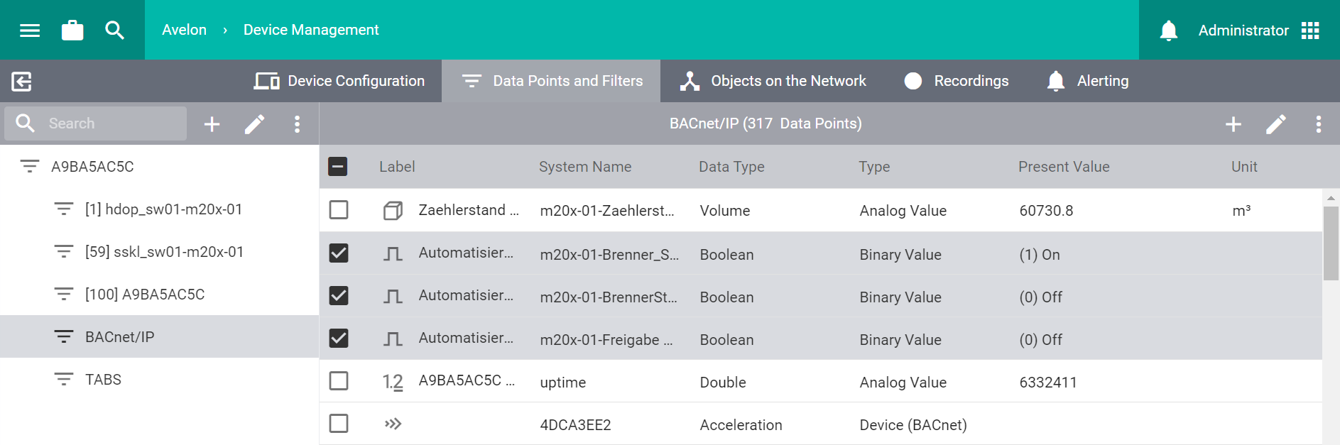
Then click on Edit Data Point at the top right in the toolbar to edit all selected data points simultaneously.
The view differs from the editor for individual data points. If the selected data points have different values for a certain property, this is displayed accordingly. When you change a property, the new value is applied to all selected data points. In principle, however, only the properties that you actually change are saved.
To return to the data point list, click on Back to Data Point List at the top right in the toolbar.
If you want to create or update multiple data points in bulk, you can import them from an external file. For more information, see Import data points.