Manage addressing systems
Addressing systems can either by created manually, or by importing a solution from a third party.
Create new addressing system
To create a new addressing system, go to the tab Addressing Systems in device management. In the sidebar on the left, click on Add ▸ Addressing System. Note that a new addressing system is created, and below it, a new project structure. We will describe project structures in detail later in this chapter. For now, make sure the new addressing system is selected, then enter a new name for it.
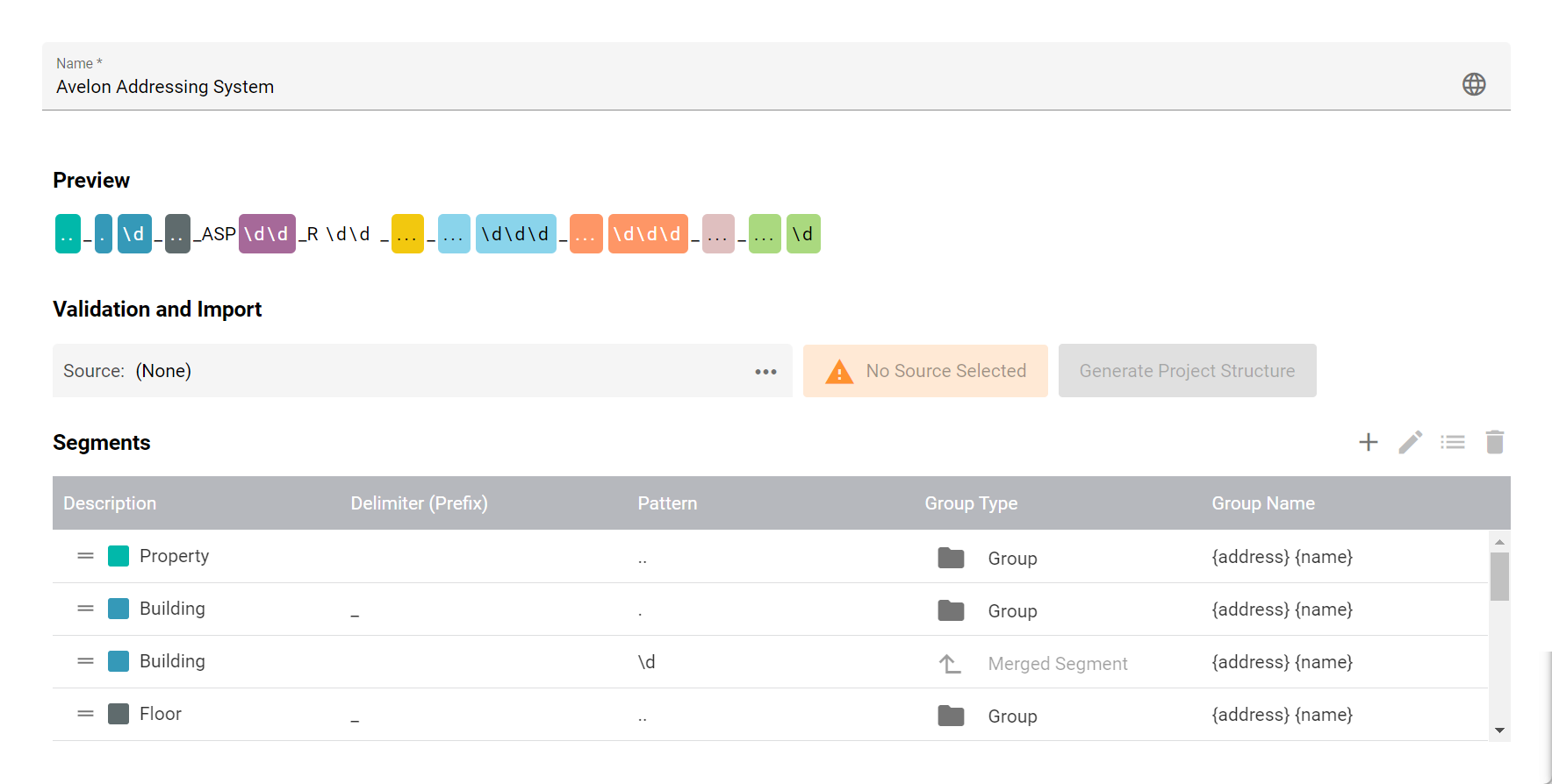
Segments
Each addressing system consists of a number of segments, each of which defines a portion of the identifier of a component in your system (such as buildings, floors, rooms, trades, data points, etc.).
To add a segment to your addressing system, click on Add in the Segments section and configure it in the following dialog.
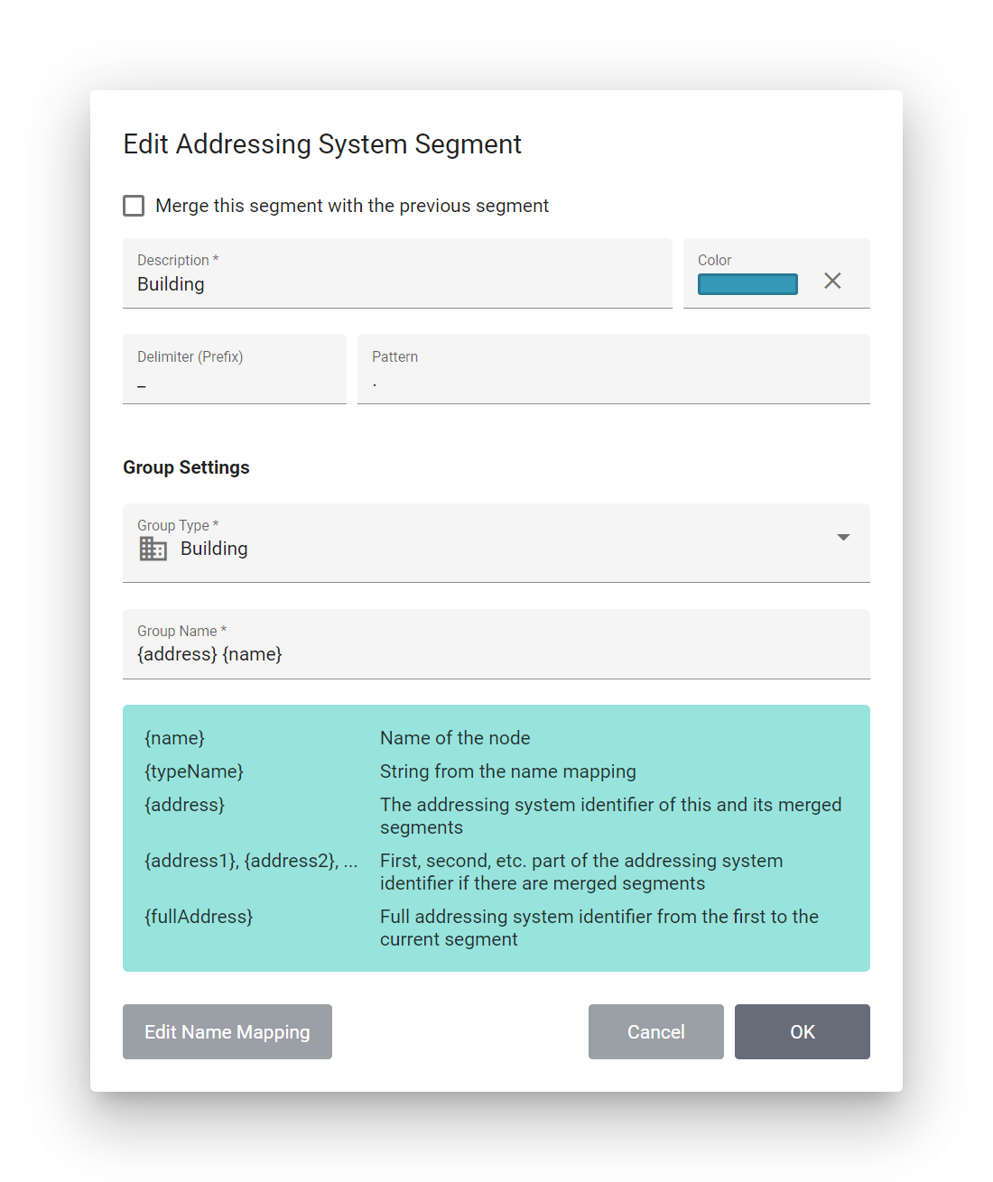
- Merge this segment with the previous segment
See section Merged segments below.
- Description
The description will be displayed alongside the color to identify the segment. You can hover over a segment to show its description.
- Color
The color will be displayed alongside the description to identify the segment.
- Delimiter (Prefix)
The character or string that separates this segment from the previous segment. Frequently used delimiters are
_and-. If you don’t need a delimiter, leave this field empty.- Pattern
A regular expression that defines the exact format of the segment. The delimiter defined in the field Delimiter should not be included in this pattern.
Examples
Three arbitrary characters:
...An uppercase letter, followed by a digit:
[A-Z]\dTwo letters, followed by a dot and 1-3 digits:
[A-Za-z]{2}\.\d{1,3}
This pattern is required by the system to be able to identify individual parts of an object’s identifier and match it to the segment. It will also be used by the system to generate the proper project structure (see Generate project structure).
If you want to generate intermediary groups in your project structure for which there is no corresponding part in the addressing system, you can leave this field empty.
Group settings
- Group type
Define the type of group that should be created for this particular segment in the addressing system. Select a dedicated type like Portfolio, Real Estate or Building only for the segments that correspond to these types. For all other segments, please select the default type Group.
- Group name
Enter the name that should be used when generating the a group or data point filter for this segment. You can customize the name as required and even use placeholders that will be filled automatically with the correct string from the import file or the Name mapping.
You can use the following placeholders:
Placeholder |
Description |
|---|---|
|
The system will search for an appropriate name in the following places and use whichever value is found first:
|
|
The system will search for an appropriate type name in the following places and use whichever value is found first:
|
|
The full addressing identifier from the first to the current segment. |
|
The first, second, etc. part of the addressing identifier. These are only available if there are merged segments below the current segment. |
Name mapping
Usually, the name of a group or data point filter that is generated based on this addressing system will take the name either from the imported project file or the addressing identifier itself. However, you can also define a list of key/values pairs which will be used to transform the matched part of the addressing identifier to a custom string.
Click on Edit Name Mapping on the dialog to open the Name Mapping dialog. Use the Add Entry icon at the bottom left to add new items to the map and enter a Key and a Value for each row.
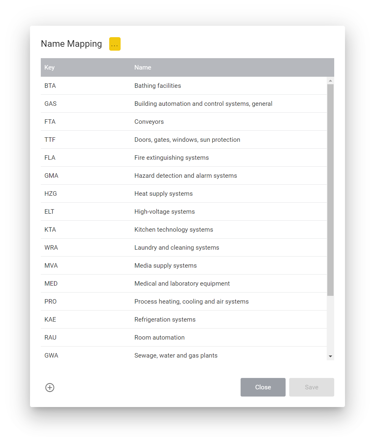
The key must correspond to a string that is captured by the Pattern of the segment.
For example, if the pattern on the segment expects three uppercase letters ([A-Z]{3}), the key must contain three uppercase letters (ABC, XYZ, etc.).
Merged segments
Sometimes you might need to create multiple segments for which you want to generate only a single element in the project structure.
For example, one segment might match the type of a component (e.g. CST for Cooling Storage), while the subsequent segment might match the sequence number of that component (e.g. 001).
If you want to generate a group in your project structure for both segments with a combined label such as CST 001, you can merge segments.
To merge segments, edit the subsequent segment and enable the option Merge this segment with the previous segment. Most options for the segment will disappear, as they will now be overriden by the preceeding segment. Confirm with OK. The Group Type column in the table will now show the text Merged Segment to indicate that this segment will be combined with the previous one to generate a single element in the resulting project structure.
You can now use the name of the merged segment in your main segment.
Select the main segment (i.e. the segment just above the merged segment) and click on Edit.
In the field Group Name, you can now use the placeholder {address1} to refer to the addressing identifier that matches the first part of the merged segment, or {address2} to refer to the addressing identifier that matches the second part of the merged segment.
Define project structure
Below each addressing system you can create one or more project structures. Project structures define what parts of the addressing system should be turned into groups or data point filters.
Instead of creating groups and data point filters manually, the system can use the project structure to automatically create them based on the information from existing data points or an import file from a third party.
While the addressing system should contain a complete definition with all components of the entire addressing system, from the portfolio or real estate at the top down to the data point level, project structures give you the flexibility to only turn specific elements into groups or data point filters.
Each project structure will contain the same segments that are defined on the addressing system, but they cannot be changed. Instead, you’ll see two additional columns of checkboxes. Select the checkbox in the column Create Group for each segment for which you want to automatically create a group in the group navigation. Similarly, select the checkbox in the column Create Data Point Filter for each segment for which you want to automatically create a data point filter.
When creating the groups and data point filters, data point filters will be automatically assigned to the groups, while unchecked segments will be ignored.
Generate groups and data point filters
Before you generate groups and data point filters based on a your addressing system, you should validate it to make sure that the addressing system satisfies the identifiers (system names) of your data points, or the project structure from a third party import file.
In the section Validation and Import, click on Data Point Filter and Data Point Selection and select a data point that you want to use to validate the addressing system.
If the data point satisfies the addressing system, the validation will succeed. You should only proceed if the validation is successful to make sure that the generated data point filters will filter the correct data points.
If the validation is successful, click on Generate Project Structure to continue to the next page.