Link
A shape can be used to navigate between different schematics or to external web pages. With the shape selected, open the Properties panel on the right hand side and select the desired Link Type in the Link section.
- Open Flyout
Opens another schematic in a window on top of the current schematic. This can be used to display additional information about a shape without leaving the current schematic, or to implement custom navigation menus.
- Navigate
Navigates to another schematic.
- Navigate by data point filter
Navigates to another schematic based on the data point filter with which the current schematic was opened.
When you configure a link with type Open Flyout or Navigate in combination with a data point filter (see below) and the user clicked on that link, you can use the data point filter as a condition for the link target of this shape.
This allows you to create links that navigate to different schematics based on the data point filter with which the current schematic was opened.
For an example on how to create these dynamic links, please refer to the section Example for dynamic links below.
- External URL
Navigates to an external URL. By default, the URL opens in the same browser tab, which means this will leave Avelon Cloud or Alcedo Inhouse (unless the URL points to a URL with the server’s hostname). To open the URL on a new tab, press Ctrl (or ⌘ on a Mac) while clicking the link. If you hold down the Shift key at the same time, the new tab opens in the foreground.
Once you have selected a type, you can configure more details about the link.
- Link Target
Only available for the two link types Open Flyout and Navigate. Select the schematic to be opened as a flyout above the current schematic or to be navigated to when the shape is clicked.
- Data Point Filter
Only available for the two link types Open Flyout and Navigate. If you select a data point filter, the system will try to automatically assign data points to the shapes on the target schematic from the selected data point filter when the link is clicked.
For each behavior rule on a shape on the target schematic, the system will search for a data point from the selected data point filter that matches the system name pattern that is defined in the behavior rule. This requires that the data point filter contains a unique data point for each system name pattern. Therefore, it’s recommended to create separate data point filters that only contain the data points that are relevant for the target schematic (e.g. that match only data points for a specific room or component that you want to display on the target schematic).
- URL
Only available for the link type External URL. Opens the specified URL.
- Table with data point filters and targets
Only available for the link type Navigate by Data Point Filter. If the current schematic is called via a link on which a data point filter is configured, clicking on this link automatically opens the link target in this table that is linked to the same data point filter. Add a separate row to the table for each data point filter that can potentially be used to call the current schematic and assign the desired link target to it in the second column.
Example for dynamic links
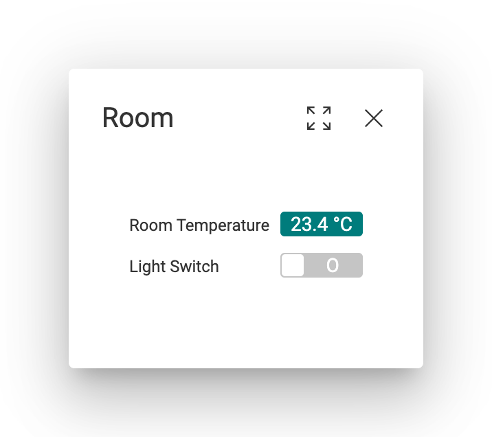
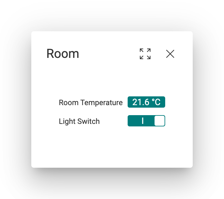
Let’s assume we have a schematic for room control, and we would like to reuse this schematic for multiple rooms in our building instead of creating separate schematics for each of them.
For the sake of simplicity, let’s assume that we have only two rooms, room 101 and room 102, and that each room only contains two data points: a temperature sensor and a light switch.
The system names of the temperature sensors are L01.HVC.RM101.TMP and L01.HVC.RM102.TMP, and the system names of the light switches are L01.LGT.RM101.SW_ST and L01.LGT.RM102.SW_ST, respectively.
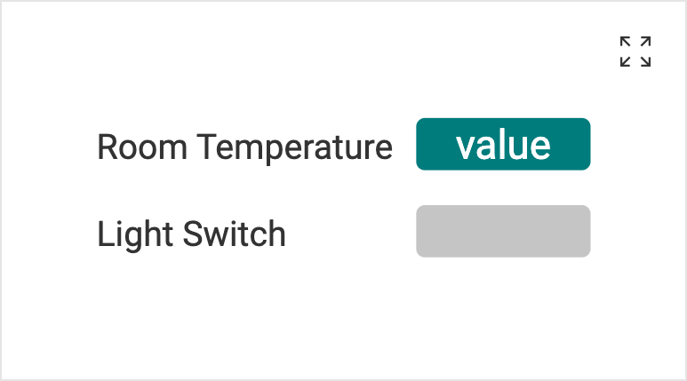
The shapes that you use on the room control schematic must have behavior rules with system name patterns that capture the respective data points.
The shape that should display the temperature value must have a behavior rule with a system name pattern that matches the temperature data points of all rooms (e.g. L\d{2}\.HVC\.RM\d{3}\.TMP), and the shape that acts as the light switch must have a behavior rule with a system name pattern that matches the light switches of all rooms (e.g. L\d{2}\.LGT\.RM\d{3}\.SW_ST).
Note that these system name patterns must be defined as regular expressions that need to match all data points of the same type (in our case all room temperatures or light switches, respectively).
Do not assign data points to these shapes manually, otherwise the automatic assignment of data points from the data point filter will not work.
Now we also need to create two data point filters – one for each room – that contain the respective data points for each room.
The data point filter for room 101 should match the system name L01.*.RM101.*, and the data point filter for room 102 should match the system name L01.*.RM102.*.
In contrast to the system name patterns on the behavior rules, these system name patterns are not regular expressions.
You can only use * as a wildcard character that matches any arbitrary sequence of characters, or ? to match an arbitrary single character.
On your building overview schematic, you can then create a link shape to both rooms. Select the link type Open Flyout or Navigate, select the room control schematic as the Link Target, and select the appropriate data point filter for the respective room.
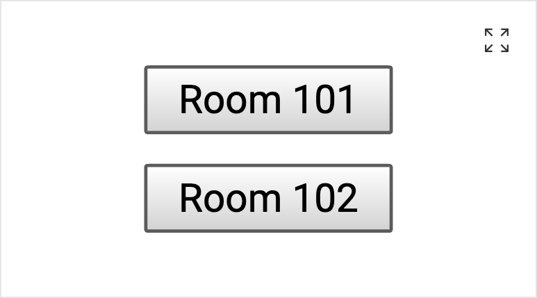
Now the two link shapes should both open the same room control schematic, but with different data points assigned to the shapes.
If you want to place a link shape on the room control schematic that navigates to another page depending on which room is currently displayed, you can do so by selecting the Navigate by Data Point Filter link type on that shape. In the table that appears, you can add each of the potential data point filters and assign the respective link target for each of them. When the link shape is clicked, the system will navigate to the schematic that is associated with the data point filter that is currently used to display the room control schematic.
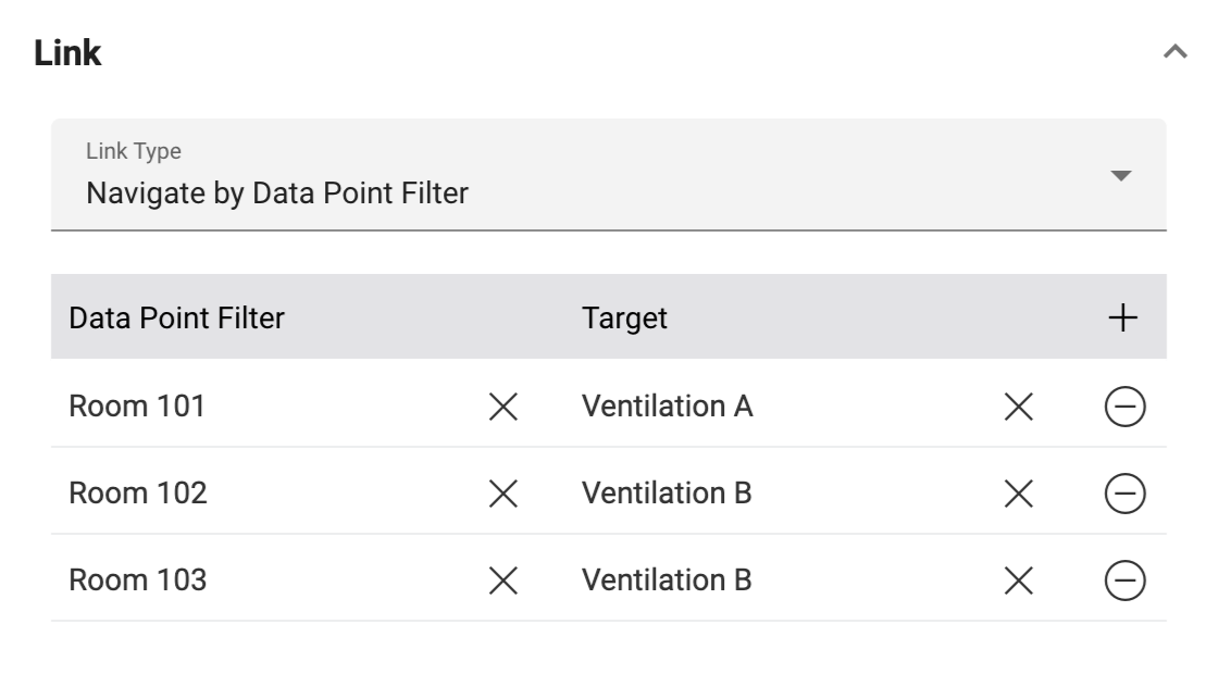
Configure each data point filter with which the schematic can be opened in the left column, and assign the respective link target for each of them in the right column.

Clicking on Ventilation will either navigate to Ventilation A or Ventilation B, depending on which room link was selected initially.