Gradient background on schematic widgets
Warning
We strongly advise against using custom background gradients. Custom colors don’t adapt to the current light or dark mode of the operating system or the user’s preference, which might lead to reduced readability and accessibility due to poor contrast, especially if you use shapes that actually do take the current mode of the operating system into account (see Context-aware colors).
The recommended setting is to leave the background color undefined, so that the browser can automatically find the best matching background color for the current mode, and not to use a gradient background with custom colors. This usually results in the best contrast.
If you still want to add a custom gradient and accept the potential usability issues, follow these steps:
Create a custom shape with a gradient fill. If possible, use colors with a high transparency value, so that the background color of the browser can still shine through, which will help mitigate the contrast issues. Set the width and height of the SVG to 3 times the size of the schematic page, to make sure that the entire background will be covered, regardless of the widget’s zoom level. You’ll find an example at the bottom of this page.
Go to your schematic. Disable the option Adapt page size to contents in the Properties side panel and set a fixed page size, which should be 3 times smaller than the size of the gradient shape.
Place the gradient shape on the schematic and send it to the back so that all other shapes are displayed in front of it.
With the shape still selected, enable the option Lock shape in the Properties side panel.
Make sure that the X position of the shape is set to \(-(\text{page width} / 3)\) and Y is set to \(-(\text{page height} / 3)\). If done correctly, the linear gradient should extend beyond the borders of the schematic on all sides. When you quit editing mode, the schematic will be centered on the actual page size, and the gradient will cover the entire background.
Example
This example assumes that the schematic page is 1920 × 1080 big, so the size of the shape should be set to 5760 × 3240, and its X and Y position should be set to -1920 and -1080 when placed on a schematic.
<svg width="5760" height="3240" viewBox="0 0 5760 3240" xmlns="http://www.w3.org/2000/svg">
  <defs>
        <linearGradient id="CustomLinearBackground" x1="0%" y1="0%" x2="0%" y2="100%">
        <stop offset="33%" stop-color="#FFFFFF" stop-opacity="0.3"></stop>
        <stop offset="67%" stop-color="#000000" stop-opacity="0.3"></stop>
        </linearGradient>
  </defs>
  <rect x="0" y="0" width="5760" height="3240" fill="url(#CustomLinearBackground)"/>
</svg>
Note that the gradient only runs from 33 % to 67 % of the shape height. That way, we make sure that the gradient only covers the part that will be visible on the schematic at the default zoom level.
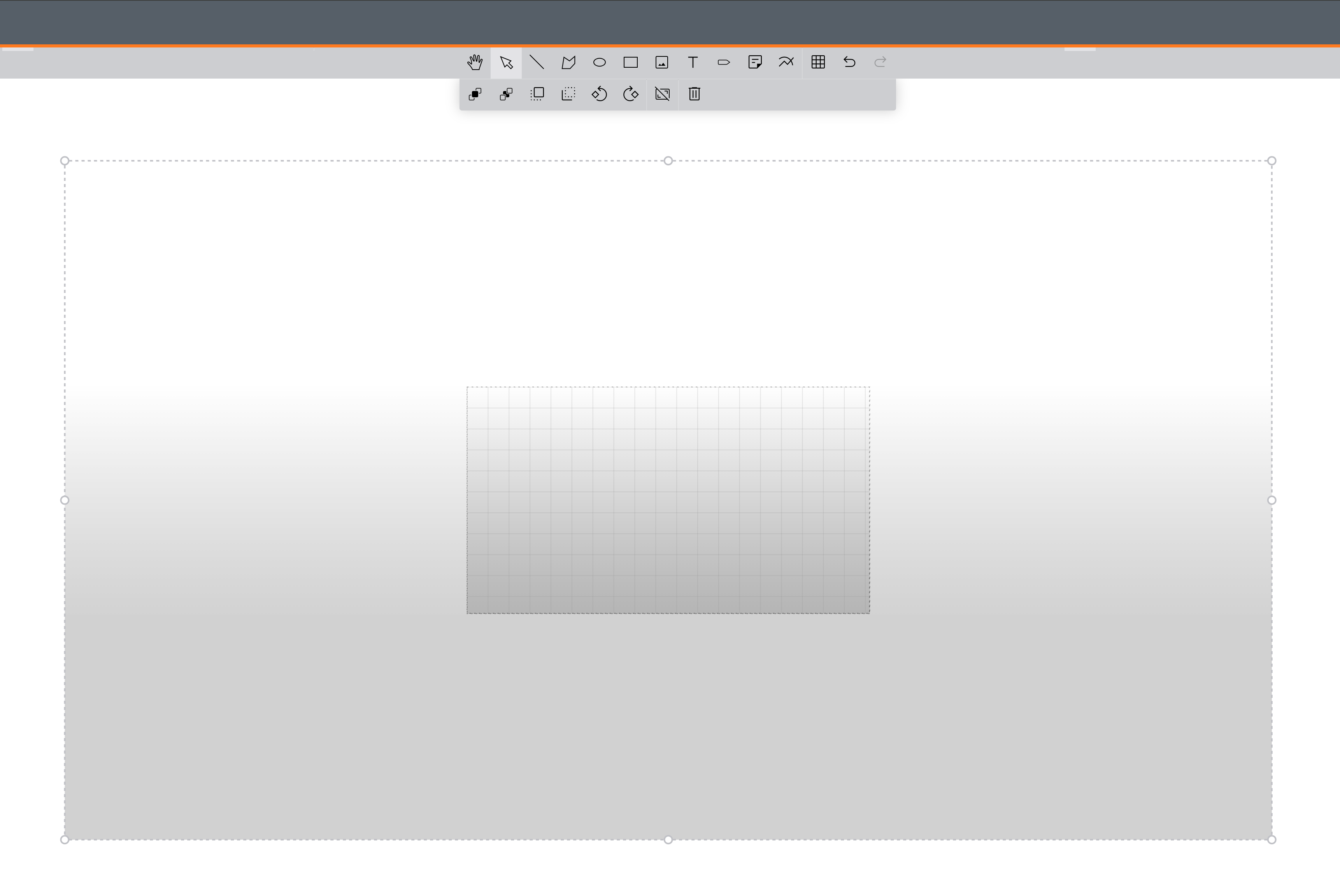

Left: Size and placement of the gradient shape (with the dashed selection border) relative to the schematic page in the center. Right: The resulting schematic at the default zoom level.